

Key Dimensions and How to Specify Compression Springs by Size
Specifying compression springs by size requires defining physical parameters that dictate both spatial fit and mechanical performance. A compression spring operates by absorbing axial compression loads and storing potential energy as its coils deflect. Correctly defining these dimensional boundary conditions ensures the spring performs within its elastic limit while working reliably within the surrounding housing or over internal guide components.
When defining a spring for production, engineers evaluate several primary geometric attributes:
- Outer Diameter (OD): The maximum physical width measured across the outer edges of the coils.
- Inner Diameter (ID): The clear cylindrical space inside the coils, calculated as OD – 2(d), where d is the wire diameter.
- Mean Diameter (D): The geometric center of the spring coil cross-section, calculated as OD – d or ID + d. This value is crucial for engineering formulas governing spring force and stress.
- Wire Diameter (d): The cross-sectional thickness of the wire. Small changes in wire diameter non-linearly affect spring rate and force output.
- Free Length (L_f): The total uncompressed length of the spring in its relaxed state.
- Solid Height (L_s): The physical height of the spring when fully compressed until all active coils touch.
- Pitch (p): The center-to-center distance between adjacent active coils in an uncompressed state.
- Active Coils (N_a): The number of coils that expand and contract freely under load.
- Total Coils (N_t): The complete count of all coils, including non-deflecting inactive end coils.
Accurate physical measurement ensures components perform correctly within mechanical assemblies. Designers routinely consult the Guide to Measuring Compression Springs to standardize measurement practices using calibrated vernier calipers, micrometer instruments, or optical measurement systems.
Measuring Outer Diameter, Inner Diameter, and Wire Gauge
Precision dimensional measurement helps avoid mechanical binding during operation. When a spring compresses, its diameter expands slightly (a phenomenon known as coil expansion under load). If a spring operates inside a bore without proper radial clearance, this expansion can cause binding against the housing wall.
When fitting a spring over a shaft, the shaft diameter must be smaller than the minimum inner diameter tolerance. Designers account for standard shaft clearance to prevent binding. Conversely, when fitting inside a cavity, the bore diameter must accommodate the maximum outer diameter, accounting for coil expansion during deflection.
To determine the approximate outer diameter expansion (Delta OD) at solid height, engineers use the formula:
Delta OD = frac{p^2 – d^2}{2 pi^2 D}
Where p represents pitch, d is wire diameter, and D is mean diameter.
Wire gauge standards must be carefully verified. Drawn spring wire sizes may follow American Wire Gauge (AWG), Washburn & Moen gauge, or standard decimal inch and metric millimeter callouts. Because material strength varies with wire thickness, specifying exact decimal dimensions rather than arbitrary gauge numbers prevents ambiguity. Precision optical comparators and digital calipers are recommended for measuring wire cross-sections to verify compliance with basic engineering drawings. Understanding these core parameters is foundational to learning What Are Compression Springs? and how they function in complex assemblies.
How End Configurations Alter Compression Springs by Size and Solid Height
The mechanical design of spring ends influences total height, seating alignment, and force delivery. Choosing a specific end style affects the number of active coils versus inactive coils, directly impacting solid height calculations.
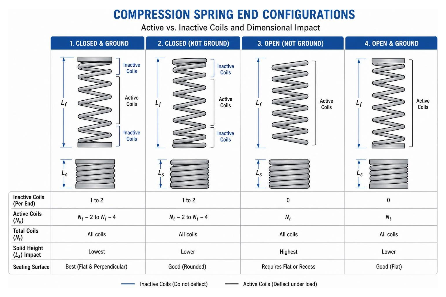
The primary end configurations include:
- Closed and Ground Ends: The end coils are flattened perpendicular to the spring axis through grinding. This creates a flat surface for uniform axial load transfer and minimizes buckling tendencies.
- Closed Ends (Not Ground): The terminal coil pitch is reduced so the wire touches the adjacent coil, but the wire surface is left round. This option is economical while still offering stable seating.
- Open Ends (Not Ground): Coils maintain a continuous pitch throughout the entire spring length. These require square mounting surfaces or recessed pockets for stability.
- Open and Ground Ends: The end coil maintains its open pitch angle but is ground flat to provide a flat contact surface.
End design directly impacts solid height (L_s) and total coil (N_t) calculations relative to active coils (N_a):
| End Configuration | Total Coils (N_t) Formula | Solid Height (L_s) Formula | Seating Stability |
|---|---|---|---|
| Closed & Ground | N_a + 2 | N_t times d | High |
| Closed (Not Ground) | N_a + 2 | (N_t + 1) times d | Moderate |
| Open & Ground | N_a + 1 | N_t times d | Moderate |
| Open (Not Ground) | N_a | (N_t + 1) times d | Low |
Reviewing detailed documentation on Compression Spring End Types helps engineers balance manufacturability, cost, and axial load transfer requirements.
Mechanics of Spring Rate, Index, and Load-Deflection Calculations
Designing compression springs by size requires balancing geometric proportions with force expectations. The spring rate (k), or stiffness, defines the load required per unit of axial deflection:
k = frac{G cdot d^4}{8 cdot D^3 cdot N_a}
Where:
- k = Spring rate (lbf/in or N/mm)
- G = Shear modulus of the material (psi or MPa)
- d = Wire diameter (in or mm)
- D = Mean coil diameter (OD – d) (in or mm)
- N_a = Number of active coils
This formula demonstrates that spring rate is highly sensitive to physical size changes: doubling the wire diameter increases spring rate by sixteen times, whereas doubling the mean coil diameter reduces stiffness to one-eighth of its original value.
The proportion between coil width and wire thickness is expressed by the Spring Index (C):
C = frac{D}{d}
The spring index directly impacts manufacturing feasibility, stress concentrations, and cost:
| Spring Index Range (C) | Manufacturing & Operational Characteristics | Feasibility Status |
|---|---|---|
| C < 4 | High internal stress; difficult to coil without damaging wire; tooling wears rapidly. | Discouraged |
| C = 4 text{ to } 8 | Preferred engineering range for compact designs; manageable stress; reliable coiling. | Optimal |
| C = 8 text{ to } 12 | Excellent manufacturability; easy to coil; predictable force profile. | Optimal |
| C > 12 | Coils become flimsy; prone to tangling in bulk shipping; high risk of spring buckling. | Caution Required |
When the spring index is tight (C < 5), internal stresses increase along the inner wall of the spring wire due to coil curvature. Engineers calculate the Wahl Correction Factor (K_w) to adjust for these localized shear stresses:
K_w = frac{4C – 1}{4C – 4} + frac{0.615}{C}
Applying this factor ensures that the spring operates safely within its yield stress limits, preserving long-term fatigue life under cyclic loads. Detailed calculation guidelines are outlined in How to Calculate Spring Rate for Compression Springs.
Standard Sizing Tolerances and Industry ASTM/ISO Standards
Precision springs require strict adherence to industry specification standards to perform reliably across production batches. Common standards include ASTM A228 (Music Wire), ASTM A313 (Stainless Steel), and international standards such as DIN 2095 and ISO standard frameworks.
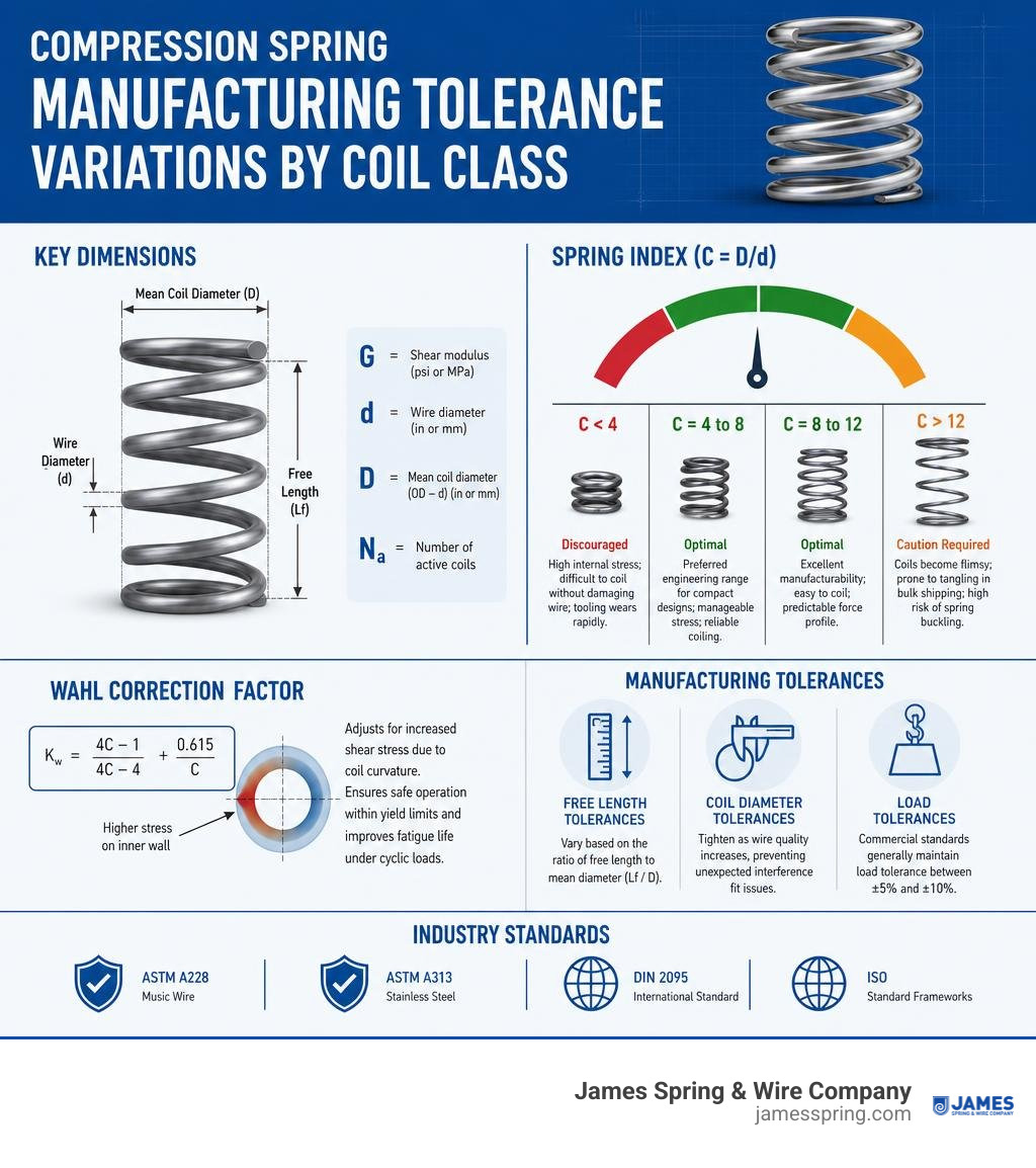
Manufacturing tolerances dictate acceptable variations in key metrics:
- Free Length Tolerances: Vary based on the ratio of free length to mean diameter (L_f / D).
- Coil Diameter Tolerances: Tighten as wire quality increases, preventing unexpected interference fit issues.
- Load Tolerances: Commercial manufacturing standards generally maintain a load tolerance between pm 5% and pm 10%, depending on the total number of active coils and material consistency.
Selecting Compression Springs by Size for Specific Load and Space Constraints
Designing within constrained physical envelopes requires addressing slenderness limits and lateral stability. The slenderness ratio represents the uncompressed length divided by the mean diameter:
text{Slenderness Ratio} = frac{L_f}{D}
If the free length exceeds 4 times the mean diameter (L_f / D > 4), the spring is susceptible to column buckling under axial load.
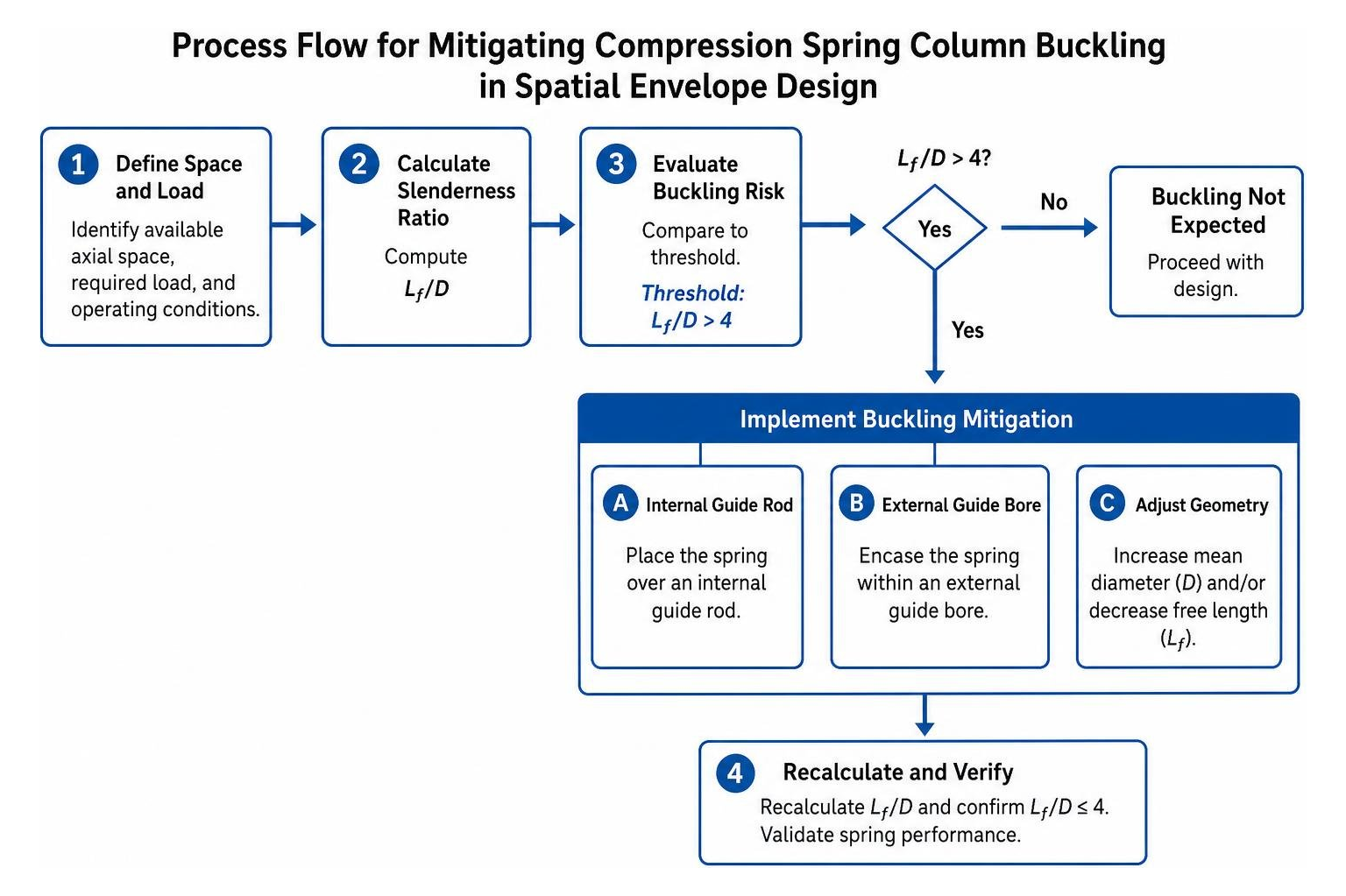
When design parameters predict buckling, engineers implement key remedies:
- Placing the spring over an internal guide rod.
- Encasing the spring within an external guide bore.
- Adjusting geometric dimensions to increase the mean diameter or lower the free length.
Engineers rely on comprehensive checklists, such as the Spring Design Checklist, to ensure all boundary parameters, maximum stroke limits, and stress thresholds are evaluated prior to tool setup.
Comparing Stock vs. Custom-Sized Springs for OEM Applications
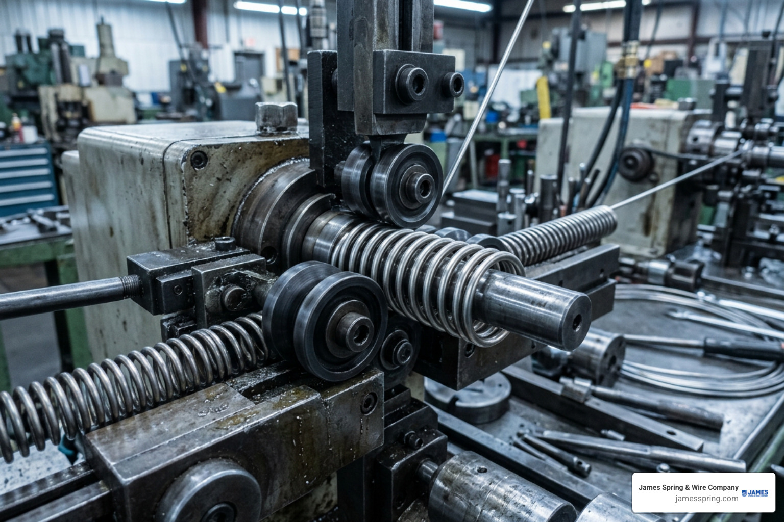
When selecting compression springs by size, designers decide between off-the-shelf stock springs and custom-engineered options.
| Metric / Consideration | Stock Compression Springs | Custom-Engineered Springs |
|---|---|---|
| Dimensional Choices | Fixed incremental catalog sizes | Fully customizable OD, ID, wire gauge, and length |
| Tooling Expenses | None | Minimal setup or specialty tooling charges |
| Material Selection | Primarily standard spring steel or 302 stainless steel | Specialized alloys (Inconel, 316 SS, Phosphor Bronze) |
| Production Lead Time | Immediate delivery | Engineered around manufacturing schedules |
| Fit in Assembly | Assembly must adapt to available catalog sizes | Spring is designed around fixed envelope constraints |
Stock components work well for early stage conceptual designs, low-volume assemblies, or non-critical mechanical linkage systems. However, relying on fixed stock sizes often forces designers to compromise on optimal spring rate, stroke length, or load output.
Conversely, custom-engineered springs allow precise alignment of wire size, pitch, end geometry, and material specifications. Engineering resources like the Spring Material Selection Handbook provide insight into selecting appropriate alloys for specialized mechanical environments.
When to Transition from Stock Catalogs to Custom Dimensions
Stock sizes can be restrictive when working within tight geometric constraints or strict performance requirements. Moving to a custom-engineered dimensional layout becomes necessary when designs require:
- High Fatigue Cycle Limits: Continuous high-speed cycling requires custom pitch geometry and controlled stress levels to prevent premature failure.
- Harsh Environmental Conditions: Corrosion-resistant alloys, such as 316 Stainless Steel or Hastelloy, are rarely available in standard stock catalogs.
- Custom Surface Finishes: Operations like passivating, shot peening (which increases resistance to cyclical fatigue), or protective electro-plating alter outer dimensional fits slightly and require tailored coil geometry. Reviewing the Impact of Surface Treatments on Compression Spring Performance helps account for these finish layers.
- Strict Mechanical Profiles: Custom variable pitch configurations or conical geometries can deliver non-linear rate curves or ultra-compact solid heights that stock parts cannot achieve.
Custom options suit demanding applications across various industries, including:
- Common Compression Spring Uses
- Popular Types of Compression Springs
- Custom Compression Springs a Popular Choice for Sporting Equipment
- Custom Compression Springs in Automotive Industry
- Medical Compression Springs Orthopedic Devices
- Low Carbon Steel Compression Limiters
Common Sizing Pitfalls in Mechanical Design
Avoiding frequent design oversights ensures reliable performance and simplifies spring manufacturing:
- Underestimating Solid Height Constraints: Designers sometimes assume solid height equals the wire diameter multiplied by active coils, neglecting inactive end coils and plating thickness. This leads to bottoming out before reaching the desired operational travel.
- Ignoring Buckling Behavior: Designing long, unguided springs with a high slenderness ratio causes structural bowing, uneven wear, side loading, and erratic force delivery.
- Confusing Active Coils with Total Coils: Failing to deduct closed end coils when calculating spring rate leads to springs that are significantly stiffer or softer than intended.
- Over-Specifying Tolerances: Demanding ultra-tight dimensional tolerances on non-critical dimensions (like free length and outer diameter simultaneously) unnecessarily increases production and inspection costs.
- Ignoring Stress Relaxation under Temperature: Standard carbon steels lose load capability at elevated temperatures. High-temperature environments require alternative materials to maintain consistent spring force over time.

Evaluating physical springs on force-versus-deflection testing machines helps confirm theoretical calculations against real-world mechanical behavior.
Frequently Asked Questions About Compression Spring Sizing
How do I interpret a spring catalog size chart?
Read column parameters systematically. Charts list critical outer diameters, compatible rod/bore dimensions, wire sizes, free length, solid height, maximum allowable load, and the calculated spring rate. Match your target load requirements at a specific stroke length to the catalog spring rate value (k = frac{F}{Delta L}).
What is the ideal spring index range for manufacturing?
An optimal spring index (C = frac{D}{d}) falls between 4 and 12. Indices under 4 introduce severe stress concentrations and make uniform manufacturing difficult. Indices over 12 yield flexible, lightweight coils prone to tangling during shipping and assembly.
How does end grinding affect free length and load capacity?
Grinding end coils creates a flat, square seating surface that improves axial load alignment and reduces structural buckling. Grinding removes small amounts of end material, lowering solid height and slightly altering the effective count of active coils compared to unground ends.
Conclusion
Selecting compression springs by size requires precise balancing of spatial limits, physical envelope parameters, and force profiles. Accurately defining wire gauge, diameter, free length, end geometry, and solid height ensures springs operate smoothly within mechanical assemblies without binding, buckling, or overstressing.
When standard catalog sizes do not meet specialized operating demands or physical space limitations, partnering with an experienced spring manufacturer ensures optimal functional performance. James Spring & Wire Company brings technical expertise to support OEM development, transitioning spring designs from initial concept through precision production. Explore engineering capabilities by visiting Compression Springs.