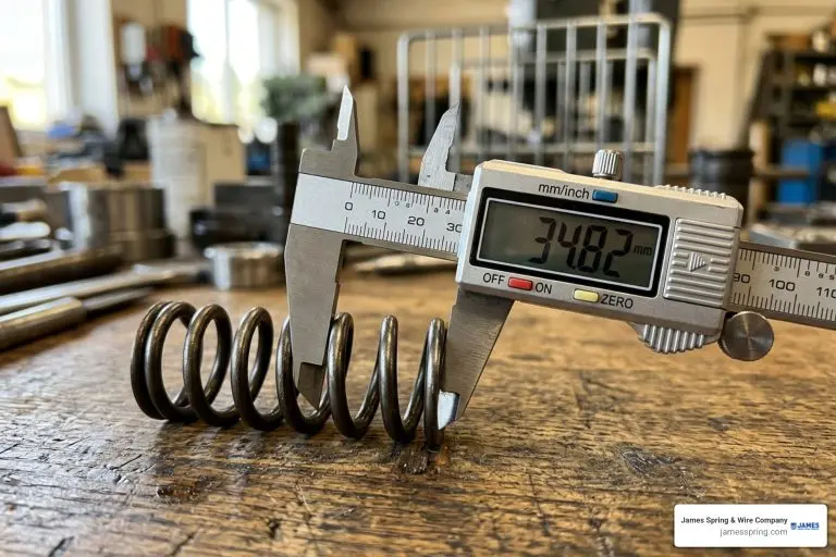


What is the Spring Constant of Springs in Series?
When multiple mechanical springs are connected end-to-end (point-to-point) along a single continuous load line, they form a spring constant of springs in series assembly. In this configuration, the physical behavior of the entire spring stack changes fundamentally compared to a single standalone spring. To understand how this works, we look at fundamental principles like The Science of Springs: How They Work and apply Hooke’s Law across the full component chain.
In a series network, any external tensile or compressive load applied at the free end is transmitted unchanged through every single component in the line. However, the overall movement or travel of the assembly is the cumulative sum of the individual spring extensions or compressions. Because total deformation increases while the internal force remains fixed, the combined system exhibits lower overall stiffness (higher mechanical compliance).
Mechanical compliance (c) is defined as the mathematical reciprocal of the spring constant (c = 1/k). While spring rates add directly when components are positioned side-by-side (in parallel), series combinations sum their compliance values directly (c_{mathrm{eq}} = c1 + c2 + dots + c_n). Understanding this relationship is critical when Calculating a Spring Constant Using Hooke’s Law in multi-component mechanical systems.
Understanding Force and Deformation Distribution
To analyze a series system accurately, consider how internal forces and displacements distribute across each component under equilibrium conditions:
- Uniform Axial Force Distribution: In a static series system of negligible mass, the force F applied at the primary load point propagates directly through every intermediate connection. If two springs (Spring 1 and Spring 2) are connected in series under load F, the force acting on Spring 1 (F1) and the force acting on Spring 2 (F2) are equal:
F_{mathrm{total}} = F1 = F2 = F - Additive Deflection (Elongation or Compression): Although each spring experiences the exact same force, each deforms according to its specific stiffness (ki). The overall system displacement (x{mathrm{total}}) equals the sum of the individual displacements (x1, x2, dots, xn):
x{mathrm{total}} = x1 + x2 + dots + x_n
Because weaker springs experience greater deflection under the same applied load, soft components in a series stack undergo significantly higher strain than stiff components.
Formula Derivation for Spring Constant of Springs in Series
We can derive the governing mathematical expression for the equivalent spring constant by combining Hooke’s Law (F = k cdot x, or x = F / k) with our displacement superposition equation.
Starting with the total displacement identity for n springs in series: x_{mathrm{total}} = x1 + x2 + dots + x_n
Substituting Hooke’s Law for each displacement term: frac{F_{mathrm{total}}}{k_{mathrm{eq}}} = frac{F1}{k1} + frac{F2}{k2} + dots + frac{Fn}{kn}
Since force is identical across all components (F_{mathrm{total}} = F1 = F2 = dots = Fn = F), we divide the entire equation by F: frac{1}{k{mathrm{eq}}} = frac{1}{k1} + frac{1}{k2} + dots + frac{1}{k_n}
This reciprocal relationship shows that the total stiffness of a series system is governed by compliance addition. To explore more about fundamental spring parameters and metric definitions, refer to our overview on the Spring Constant.
How to Calculate Equivalent Spring Rate in 3 Easy Steps

Calculating the effective rate of a series spring combination is straightforward when broken down into three distinct steps. Following this workflow prevents common algebraic and unit conversion errors during product development.
Step 1: Identify Spring Rates and Convert Units
Before performing any calculation, collect the individual spring constants (k1, k2, dots, k_n) for each spring in the assembly. Verify that all values share identical units of force per length. Standard units include:
- Newtons per meter (mathrm{N/m}) or Newtons per millimeter (mathrm{N/mm})
- Pounds-force per inch (mathrm{lbf/in})
If one spring is rated in mathrm{N/mm} and another in mathrm{N/m}, convert all rates to a common unit system prior to entering them into the reciprocal formula. For a detailed breakdown of spring rate dimensions and unit conversions, review Spring Constant Dimensional Formula 101. Additionally, ensure all springs operate within their linear elastic limits so that Hooke’s Law remains valid across the expected travel.
Step 2: Apply the Reciprocal Formula for Spring Constant of Springs in Series
Insert the individual spring rates into the reciprocal summation equation: frac{1}{k_{mathrm{eq}}} = sum_{i=1}^{n} frac{1}{ki} = frac{1}{k1} + frac{1}{k2} + dots + frac{1}{kn}
For assemblies consisting of exactly two springs, you can streamline the calculation using the algebraic product-over-sum shortcut: k_{mathrm{eq}} = frac{k1 cdot k2}{k1 + k2}
For a special case involving n identical springs, each having an individual spring constant of k, the equivalent spring constant simplifies directly to: k_{mathrm{eq}} = frac{k}{n}
For instance, connecting two identical springs of 100 mathrm{N/m} in series reduces the effective assembly stiffness by half to 50 mathrm{N/m}. Connecting three identical 100 mathrm{N/m} springs cuts the overall system stiffness to one-third (33.33 mathrm{N/m}). When selecting individual components for complex assemblies, consult our guide on How to Calculate Spring Rate for Compression Springs.
Step 3: Invert the Total Sum to Find Effective Stiffness
When using the general reciprocal formula for three or more springs, calculate the numerical sum of the reciprocals, then invert the result (1 / text{sum}) to solve for k_{mathrm{eq}}. Leaving the final answer as 1/k_{mathrm{eq}} is one of the most frequent mathematical errors in spring rate calculations.
Worked Calculation Example
Consider a mechanical assembly using three springs connected in series with individual spring rates of k1 = 15 mathrm{N/m}, k2 = 10 mathrm{N/m}, and k_3 = 5 mathrm{N/m}.
- Calculate the individual reciprocals:
frac{1}{k1} = frac{1}{15} approx 0.0667 mathrm{m/N}
frac{1}{k2} = frac{1}{10} = 0.1000 mathrm{m/N}
frac{1}{k_3} = frac{1}{5} = 0.2000 mathrm{m/N} - Sum the reciprocals:
frac{1}{k_{mathrm{eq}}} = 0.0667 + 0.1000 + 0.2000 = 0.3667 mathrm{m/N} - Take the reciprocal of the total sum:
k_{mathrm{eq}} = frac{1}{0.3667} approx 2.73 mathrm{N/m}
Notice that the final equivalent stiffness (2.73 mathrm{N/m}) is strictly lower than the softest spring in the stack (5 mathrm{N/m}).
Calculating Individual Extension and Stored Energy
Once k_{mathrm{eq}} is established, you can solve for individual deflections and elastic potential energy distribution across the network under an applied load F. Learn more about evaluating system travel in our article on Calculating Spring Deflection.
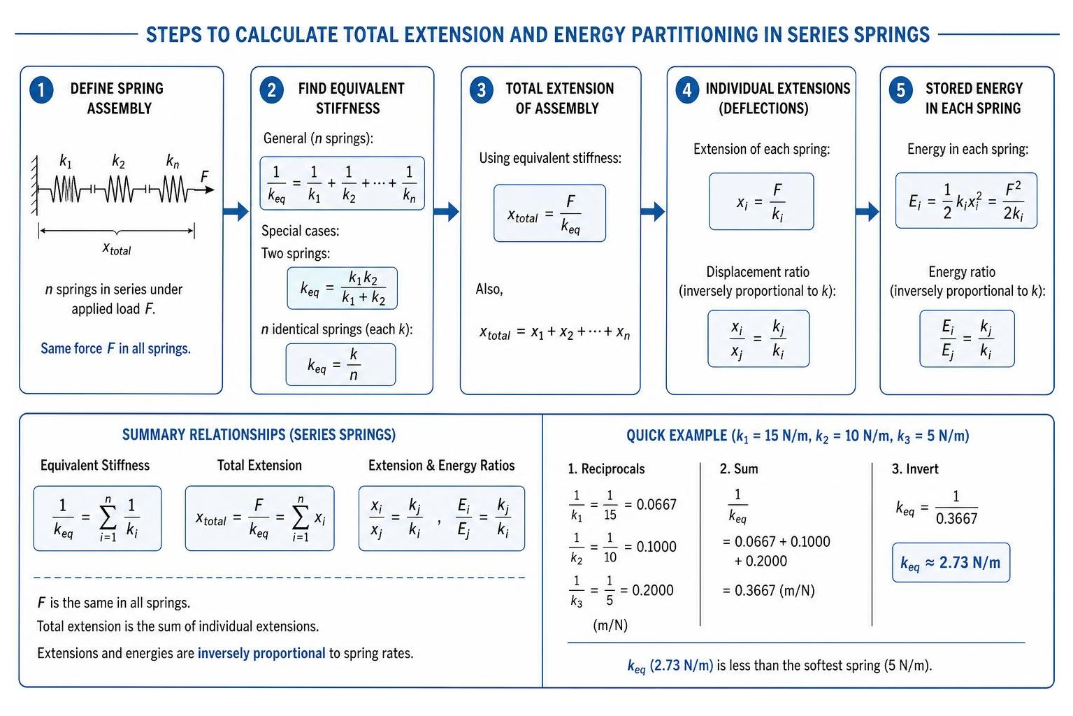
- Displacement Ratio: Since F = k1 x1 = k2 x2, the ratio of extensions between any two springs in series is inversely proportional to their individual spring rates:
frac{x1}{x2} = frac{k2}{k1} - Stored Energy Ratio: The elastic potential energy stored in a spring is E = frac{1}{2} k x^2 = frac{F^2}{2k}. Because force F is uniform across all series components, the stored energy ratio is also inversely proportional to their spring rates:
frac{E1}{E2} = frac{k2}{k1}
Thus, the softer spring stores a proportionally larger fraction of the overall potential energy and undergoes greater total displacement.
Key Principles and Common Applications of Series Springs

When integrating series spring combinations into OEM products, several physical principles dictate assembly behavior:
- Systemic Flexibility Increase Rule: Adding another spring in series always decreases total system stiffness, regardless of how stiff the added spring is.
- Dominance of the Softest Spring: The softest spring (lowest k) contributes the largest share of compliance (1/k). Consequently, the equivalent rate of the system is heavily weighted toward and bounded below the softest spring’s rate.
- Physical Spring Geometry (Cutting a Spring in Half): A single continuous helical spring behaves physically as a chain of smaller spring segments connected in series. The spring constant of a uniform wire coil spring is given by:
k = frac{G cdot d^4}{8 cdot N cdot D^3}
where G is the material shear modulus, d is wire diameter, D is mean coil diameter, and N is the number of active coils.
Because spring rate is inversely proportional to the active turn count (N), cutting a uniform spring in half reduces N by half, doubling the spring rate of each resulting half (k_{mathrm{half}} = 2k_{mathrm{original}}). Connecting those two halves back together end-to-end in series yields: frac{1}{k_{mathrm{eq}}} = frac{1}{2k} + frac{1}{2k} = frac{2}{2k} = frac{1}{k} implies k_{mathrm{eq}} = k_{mathrm{original}}
Understanding these structural trade-offs helps designers evaluate components like What Are Compression Springs? and What is a Coil Spring? for complex mechanical assemblies.
Comparing Springs in Series vs Parallel
Mechanical designs often require choosing between series or parallel spring arrangements—or combining both into hybrid series-parallel spring trees.
| Parameter / Feature | Springs in Series | Springs in Parallel |
|---|---|---|
| Physical Arrangement | Connected end-to-end along a single line | Connected side-by-side between common plates |
| Force Distribution | Equal force across all springs (F_{mathrm{total}} = F1 = F2) | Force shared across springs (F_{mathrm{total}} = F1 + F2) |
| Deflection Distribution | Deflections add (x_{mathrm{total}} = x1 + x2) | Equal deflection across all springs (x_{mathrm{total}} = x1 = x2) |
| Equivalent Rate Formula | frac{1}{k_{mathrm{eq}}} = frac{1}{k1} + frac{1}{k2} | k_{mathrm{eq}} = k1 + k2 |
| System Stiffness Result | Always lower than softest spring | Always higher than stiffest spring |
| Electrical Circuit Analogy | Equivalent to Capacitors in Series | Equivalent to Capacitors in Parallel |
Comparing these functional attributes helps engineers balance load capacity versus stroke length. For deeper insights into managing component pre-loads, refer to How to Calculate Spring Tension and our Compression Spring vs Extension Spring Guide.
Frequently Asked Questions
Why is the equivalent spring constant in series smaller than any individual spring?
In a series network, the applied load acts equally across every spring. Because each spring stretches or compresses independently in response to that same force, their displacements accumulate (x_{mathrm{total}} = x1 + x2 + dots). Increasing overall displacement for a given unit of applied force means the total assembly offers less resistance to movement, resulting in a lower combined spring rate (k_{mathrm{eq}} = F / x_{mathrm{total}}).
How does cutting a spring in half affect its spring constant?
Cutting a uniform spring in half reduces its active coil count (N) by 50%. Since a spring’s stiffness is inversely proportional to its active turns (k propto 1/N), halving the active turns doubles the stiffness (2k) of each individual half. Under an applied force, each turn stretches the same distance as before, but with half as many total turns, total extension is cut in half.
How do you find an unknown spring constant in a series pair?
If you know the desired target effective rate (k_{mathrm{eq}}) and the rate of one known spring (k1), rearrange the two-spring reciprocal formula to solve for the unknown rate (k2):
frac{1}{k_{mathrm{eq}}} = frac{1}{k1} + frac{1}{k2} implies frac{1}{k2} = frac{1}{k{mathrm{eq}}} – frac{1}{k1} = frac{k1 – k_{mathrm{eq}}}{k_{mathrm{eq}} cdot k_1}
Inverting yields the direct working equation: k2 = frac{k{mathrm{eq}} cdot k1}{k1 – k_{mathrm{eq}}}
Example Calculation
If a system requires an effective rate of k_{mathrm{eq}} = 20.0 mathrm{N/m} and utilizes a known spring of k_1 = 61.0 mathrm{N/m}:
k_2 = frac{20.0 cdot 61.0}{61.0 – 20.0} = frac{1220}{41.0} approx 29.76 mathrm{N/m}
Conclusion
Calculating the spring constant of springs in series relies on compliance addition: sum the reciprocals of the individual spring constants and invert the total to obtain the system’s effective rate. Because force remains uniform while individual deflections accumulate, a series stack is always more flexible than any single spring within it. Managing these mechanical relationships ensures accurate total stroke, predictable force delivery, and reliable service life across OEM applications.
James Spring & Wire Company brings over 60 years of in-house manufacturing expertise to custom spring and wire form designs. Working as an experienced OEM manufacturing partner, the company produces custom springs, compression springs, extension springs, torsion springs, precision wire forms, HVAC air filter clips, and other formed wire components. James Spring delivers consistent precision components tailored to exact engineering specifications.
For technical guidance on spring design or to submit design specifications for custom OEM components, Request a Quote for Custom Spring Solutions from James Spring & Wire Company today.